Deciphering the Anatomy of a Riding Saddle
A Visual Breakdown of the Western Saddle
A poorly fitted Western saddle can cut a horse’s stride by 15 percent! I have seen that figure in gait analysis. Deciphering the anatomy of a riding saddle starts with the horn above the pommel and the cantle at the rear. Between them, the seat holds a subtle dish. The skirt hides the tree and gullet. Follow the fender to the stirrup leather; a cinch ring secures the latigo. Every horse riding equipment diagram I trust shows these landmarks.
- The horn, a handhold for roping.
- The cantle, which sets rider position.
- The fender, shielding the stirrup leather.
The mystery lies beneath the skirt, where bars meet the horse’s back. No diagram captures that fit; palpation reveals it!
English Saddle Components and Their Functions
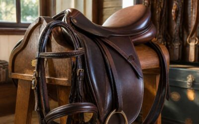
Two saddles, two philosophies. The English saddle, stripped of the Western’s horn and bulky skirt, prioritizes close contact between rider and horse. It is a minimalist marvel, designed for disciplines like dressage and show jumping where precise communication is paramount. Understanding its components begins with the tree, the rigid base that distributes the rider’s weight, and continues with the panels, those padded cushions on the underside that protect the horse’s spine. It is a system of elegant engineering, and a proper horse riding equipment diagram will show you its architecture clearly.
The layout is more direct than its Western cousin. Without the obscuring fender, the stirrup leathers run straight from the stirrup bars, which are discreetly positioned on the seat. This design allows the rider’s leg to hang naturally, a subtle but significant difference in riding posture.
A closer look at the parts reveals the function of each element:
– The pommel, which is the front arch of the saddle, forms a safe, low profile.
– The cantle, at the rear, is lower and less prominent than on a Western saddle.
– The flaps, which are the large leather panels, protect the rider’s legs and provide a stable base.
– The girth straps, recessed beneath the flaps, secure the saddle without interfering with the rider’s leg.
– The knee rolls, those padded additions on the front of the flaps, offer support for the rider’s knees during intense work.
The stirrup leathers, as mentioned, pass through the bars on the seat and are adjusted by a simple buckle. Everything is about removing bulk to enhance sensitivity. The close contact design means you can feel the horse’s every breath and movement. It is a different language of horsemanship, and a good horse riding equipment diagram helps you read it fluently. The saddle pad must sit flush against the panels and tree to maintain balance, ensuring the rider’s weight is perfectly distributed across the horse’s back.
Identifying the Tree and Its Role in Fit
The tree rarely appears in product photos, yet it is the single most influential component in saddle fit. A horse riding equipment diagram may show the visible leather and metal parts, but the tree is the internal frame that determines whether the saddle fits or fails. Its gullet width, bar angle, and curvature must align with the horse’s conformation.
A narrow tree pinches the withers and restricts shoulder movement. A wide tree rocks sideways, creating pressure points. The tree angle should mirror the shoulder blade’s slope, allowing full stride without interference. Spring steel trees flex subtly, while timber trees offer rigid support for heavier workloads.
Fit indicators to inspect:
- Symmetrical panel contact along both sides of the back
- Even pressure distribution across the tree bars
- Gullet clearance above the spinous processes
South African horses vary widely in conformation. The Boerperd and the Nooitgedacht carry different shoulder shapes, so one tree cannot suit every mount. Riders must evaluate the fit with the horse saddled and moving.
Stirrup Bars, Fenders, and Leathers Explained
Stirrup bars are the structural anchor points of the saddle. They hold the fenders or leathers, yet most riders never inspect them. A horse riding equipment diagram often labels these parts, but the mechanics deserve attention. The bar’s position dictates how your leg falls. Too far forward, you brace against the pommel. Too far back, your knee drifts past the flap.
Western fenders are wide straps that absorb shock, while English leathers are thinner and adjustable. Both rely on a safety release mechanism on the bar, which opens during a fall.
Signs of wear on stirrup bars include:
- Corroded metal from sweat
- Loose stitching on the leather attachment
- Cracking around the rivet holes
Every component transmits force from your foot to the horse’s barrel. Ignore them, and a broken stirrup leather becomes a dangerous surprise.
Girth, Cinch, and Connecting Mechanisms
One loose cinch costs a rider three seconds of control, enough time for a horse to spin and unseat you. I have inspected tack after such failures, and the pattern repeats: worn stitching, stretched holes, ignored buckles.
In the horse riding equipment diagram, the girth and cinch appear passive. They are not! The connecting mechanisms, billets and latigo, take the entire weight of the rider and saddle. Their angles shift with every stride, creating friction and wear.
The typical failure points are:
- the billet strap’s attachment to the tree
- the cinch ring’s edge
- the buckle’s tongue
Bridle and Bit Diagrams for Clear Understanding
Parts of a Snaffle Bridle with Visual Labels
The bridle is the primary control system for a horse’s head and mouth, yet its assembly can appear deceptively complex for a new rider. A clear horse riding equipment diagram for a snaffle bridle turns this jumble of straps into logical, interconnected parts. Each component has a specific role, and understanding the visual layout prevents incorrect fitting, which can cause discomfort or miscommunication with the horse.
When examining a labelled illustration, the structure becomes intuitive. The parts work in harmony, and the diagram helps you locate each one quickly. You can see how the strap that goes over the poll connects to the cheekpieces, which then hold the bit.
- Headpiece: sits behind the ears.
- Browband: prevents the headpiece from sliding forward.
- Throatlatch: secures the bridle behind the jaw.
- Cheekpieces: adjust the height of the bit.
- Bit: rests on the bars of the mouth.
- Reins: the rider’s direct contact point.
By following the line from the headpiece down to the bit, you begin to see how the connection forms. A good horse riding equipment diagram also labels the keepers and buckles, which are small but vital for neatness and safety. Visual labels remove guesswork, ensuring the equipment functions as designed. This clarity is essential before you ever place the bridle on a horse, as a correctly assembled headpiece and bit create a clear line of communication between your hands and the horse’s mouth.
Curb Bits and Their Diagrammatic Differences
When you move from a snaffle to a curb bit, the horse riding equipment diagram changes in subtle ways. The curb bit features a shank that extends below the mouthpiece, creating leverage. This leverage amplifies the rider’s rein pressure, but it also changes the points of contact on the horse’s head. A proper diagram labels the purchase, the shank, and the curb chain separately, because each part alters the action.
Consider a simple comparison:
- The snaffle applies direct pressure to the corners of the mouth.
- The curb applies pressure to the bars, the poll, and the chin groove simultaneously.
That multi-point contact is why curb bits demand a more experienced hand! A clear horse riding equipment diagram for a curb bit shows how the cheekpieces attach above the purchase rather than directly to the mouthpiece. This changes the entire balance of the bridle.
Headstall, Browband, and Throatlatch Anatomy
“Treat the headstall like a set of reins for your thoughts,” an old Transvaal horse master once told me, “because every strap has a story to tell.” When you study a horse riding equipment diagram, the bridle’s anatomy is a map of communication. The headstall, often called the crownpiece, is the foundation that drapes over the poll. It holds the entire assembly aloft, cradling the sensitive area behind the ears. This single strap bears the weight of the bit and the buckles that connect to the cheekpieces.
The browband acts as a stabilizing force across the forehead. It prevents the headstall from sliding forward or backward, keeping the bit’s position consistent in the mouth. A proper horse riding equipment diagram will show how it threads through the keepers, those small leather loops that hold everything in neat alignment. Beneath the throatlatch defines the bridle’s balance point. This strap runs from the headstall, beneath the throat, and back to the offside cheekpiece. It does not tighten like a cinch; rather, it rests snugly enough to prevent the bridle from slipping off over the head during mounting or feed time.
Without this trio working in concert, the bit’s action is compromised in an instant. The throatlatch must be adjusted with care, allowing room for one hand to slide between it and the horse’s windpipe. This anatomy translates directly to the bit’s behaviour in the mouth. Consider the visual breakdown of these components:
– The headstall must be polished and supple to avoid chafing the poll.
– The browband sets the width, ensuring the cheekpieces hang straight.
– The throatlatch secures the entire ensemble, yet demands slack for comfort.
In the South African climate, where heat and dust test leather daily, these strap connections require scrutiny during regular checks. A worn browband keeper can twist the entire alignment, altering the pressure points we discussed earlier. The rider who memorizes the diagram’s geometry gains a better feel for the horse’s head carriage. That understanding starts with this simple, often overlooked region of the tack.
Reins: Split, Curb, and Center Rein Configurations
The horse riding equipment diagram often obscures the rein system, yet this is where the rider’s hands meet intent. Split reins run independently from each bit ring, ending in loose falls. Curb reins attach to the lever arm below the mouthpiece, amplifying pressure with a chain or strap. Center rein configurations, common in driving, create a single line from the bit’s centre.
When reading a diagram, trace the path. Split reins allow one-handed neck reining, while curb reins demand a subtle turn of the wrist. Center reins shift balance forward. Each configuration changes the leverage.
- Split reins: direct contact, independent seat.
- Curb reins: indirect, leverage-based.
- Center reins: symmetrical, precise.
Yet the same horse riding equipment diagram that shows these straps must also show their adjustment, because a rein’s length dictates its story.
Rider Protection Equipment Illustrated
Helmet Structure Diagram: Shell, Liner, and Straps
According to the South African Equestrian Federation, head injuries account for nearly 20% of all riding accidents. A horse riding equipment diagram that focuses on protective gear reveals the quiet engineering beneath the velvet cover. The outer shell, often made of polycarbonate or ABS plastic, serves as the primary defence against impact. Beneath it, an expanded polystyrene liner absorbs the force of a fall by crumpling, layer by layer. Meanwhile, the harness system, which includes the chin strap and a rear adjustment dial, ensures the helmet stays immobile.
- Shell: distributes concentrated impact over a wider area
- Liner: crushes to reduce kinetic energy
- Straps: secure the fit and resist rotational motion
I find it sobering that without this layered structure, a rider’s head is exposed to preventable trauma. Reading a horse riding equipment diagram such as this one clarifies why each component matters, and it offers a clear reminder that protection is never accidental.
Body Protector and Back Shield Mapping
When a horse falls backward, the rider’s torso absorbs force that no helmet can deflect. The body protector operates on a different principle entirely. It distributes kinetic energy across a rigid foam matrix, preventing concentrated pressure on the vertebrae and internal organs. Every rider who has walked away from a rotational fall understands this equipment not as gear, but as a transaction between physics and survival. According to a study published in the South African Journal of Sports Medicine, spinal injuries account for roughly 12% of equestrian trauma cases, and the majority of these involve the thoracolumbar region.
The structure of a quality body protector, as revealed in any comprehensive horse riding equipment diagram, is a study in layered defense:
– The impact-absorbing foam core: Viscoelastic or closed-cell foam that compresses under force, dissipating the energy before it reaches the spine.
– The flexible outer shell: A polymer coating that prevents sharp objects from penetrating the foam, while allowing full articulation of the torso.
– The posterior shield: A segmented panel that covers the coccyx and sacrum, areas frequently fractured when a rider is thrown backward onto a jump standard or arena surface.
The back shield deserves particular attention. It is connected via adjustable side panels that must rest flush against the ribs. If there is a gap between the shield and the rider’s spine, the protection becomes theoretical. The foam requires contact to transfer energy. This is why fitting a body protector is a personal undertaking, one that mirrors the complexity of the gear itself. A rider can study a horse riding equipment diagram and learn the names of every panel, but true understanding arrives when they feel the difference between a plate that shifts and one that holds firm under their own weight. Protection, when it works, should be felt precisely in the moments you hope never to experience.
Riding Boots: Anatomy of Heel, Sole, and Shaft
Riding boots are the rider’s lower limb protection, and their anatomy is as deliberate as any panel on a protective vest. The heel’s height prevents the foot from sliding through the stirrup, a design born from the physics of a fall. The sole, often leather or rubber, gives grip while allowing a clean release from the iron. The shaft supports the calf and ankle, reducing compression against the horse’s side.
In a horse riding equipment diagram, you can trace how each element addresses a specific risk. The heel raises the toe, the sole controls rotation, and the shaft distributes pressure over a wider surface.
- The heel locks the foot’s position.
- The sole balances traction and release.
- The shaft absorbs contact force.
Gloves and Whips: Grip Points and Safety Zones
A rider’s hands are mapped across two instruments: the glove and the whip. In any horse riding equipment diagram, the glove shows its purpose as a sensor, while the whip functions as an extension of intent. The glove’s palm uses a textured grip material, often a synthetic leather, to prevent rein slippage during a strong pull. Knuckle reinforcement protects against friction from the leather. The whip, by contrast, is a study in leverage. Its shaft flexes to deliver a precise tap, not a strike, and the popper at the end creates a sharp sound that travels on the air.
This equipment creates a direct feedback loop between rider and horse.
– Glove grip: Maintains contact through sweat and tension.
– Whip balance: The weight is distributed to allow a soft wrist.
– Finger articulation: Allows independent rein management without a heavy hand.
Both tools demand a quiet, steady hold from the rider to be effective.
Spurs: Diagram of Shank, Rowel, and Attachment
The spur is a quiet instrument with a reputation for punishment. In any horse riding equipment diagram, the spur shows three parts: the shank, the rowel, and the attachment. The shank is the neck extending backward; its length dictates how far the heel must rise before contact. A shorter shank gives immediacy, a longer one demands precision.
The rowel, a rotating disc with points, is no weapon. Applied correctly, it asks for engagement with gentle pressure. The attachment, a leather strap over the instep, holds without pinching.
When I read a horse riding equipment diagram, I look for three details:
- Shank angle, which influences the horse’s response.
- Rowel movement, which should spin freely without rattling.
- Attachment fit, which must sit flush against the boot leather.
South African riders, from Karoo trails to Johannesburg arenas, use spurs as a refinement. The diagram makes plain that the spur is attention, not anger.
Horse Leg Attire and Wraps in Diagram Form
Polo Wraps and Their Layering Sequence
There is a particular quiet dignity in the careful preparation of a horse for work, a ritual that speaks to the bond between human and animal. When we consider a horse riding equipment diagram, the focus often drifts to the saddle or the bridle, yet the lower limbs deserve equal scrutiny. Polo wraps are not merely decorative; they are a functional necessity for many disciplines, offering support and protection during rigorous movement. Understanding their sequence is paramount for any rider who values the soundness of their partner.
The layering process is a study in precision and feel. You begin with the banner end of the wrap placed on the inside of the cannon bone, just below the knee. Each successive layer must overlap the previous one at a diagonal, moving downwards towards the fetlock. The pressure must be consistent and firm, yet never tight enough to restrict the joint. I have often seen the result of a poorly applied wrap, and it is never a pretty sight. A slight irregularity can create a pressure point, or worse, interfere with the delicate tendons.
Once the wrap reaches the fetlock, the sequence reverses, moving back up the leg. The final turn should end just below the knee, where you secure the velcro fasteners. The entire process demands your attention. A proper wrap should be smooth, without any wrinkles or uneven bulges.
– The wrap should start on the inside of the leg.
– Each layer overlaps the previous one by half its width.
– The pressure is consistent from top to bottom.
– The final fastening is secure but not restrictive.
The goal is a seamless compression that follows the natural contours of the leg. When finished, the polo wrap should feel like a second skin, allowing the horse to move with unencumbered grace. This attention to detail, this meticulous ritual, is where the art of horsemanship truly begins. The leg, now protected and supported, is a testament to a rider’s knowledge and care. It is a quiet component of the larger horse riding equipment diagram, but one that speaks volumes about the entire practice.
Brushing Boots and Tendon Boots Compared
The distinction between brushing boots and tendon boots appears on a horse riding equipment diagram. Brushing boots guard the inner cannon bone, absorbing the impact when a hoof clips the opposite leg. Tendon boots wrap the back of the lower limb. Padded sections shield the flexor tendons from dropped rails and knocks.
Each design reads the anatomy differently. Brushing boots prioritize the medial side, where interference occurs. Tendon boots leave the front of the leg exposed but cushion the deep structures behind it. I have seen riders mix them up. The diagram marks the zones.
- Brushing boots cover the inner cannon and fetlock.
- Tendon boots protect the rear of the leg.
- Brushing boots suit horses prone to striking themselves.
- Tendon boots suit jumping and faster work.
The horse riding equipment diagram makes the division visible. One boot manages the horse’s own movement. The other manages the environment it moves through.
Hoof Boots and Their Component Labels
Leg injuries account for a significant percentage of time lost in training, making a horse riding equipment diagram an essential tool for any serious owner. The visual mapping of a protective boot reveals a complex piece of equipment. A simple polo wrap offers support but lacks the rigid shell of a modern tendon boot. The diagram clarifies this hierarchy, showing where flexibility ends and rigid protection begins.
Hoof boots solve a different problem entirely, offering temporary or permanent alternatives to metal shoes. The components labelled on a technical drawing include the sole pad, which absorbs concussion, and the tread, which provides traction on loose terrain. These elements work in concert to protect the frog and the hoof wall.
– The sole pad sits against the bottom of the hoof.
– The tread is the durable outer layer that contacts the ground.
– The cuff secures the boot around the pastern.
– The buckles or straps allow for a custom fit.
Riders across South Africa, from the trails of the Cape to the show rings of Gauteng, rely on these diagrams to make informed purchases. A clear understanding of the component labels prevents the frustration of a boot that rubs or fails under load.
Bandage Wrapping: A Step-by-Step Visual Guide
Bandaging a horse’s leg without a horse riding equipment diagram is an act of faith, and faith rarely survives a gallop. The visual guide strips away guesswork, revealing the spiral of pressure that begins below the knee and ends above the fetlock. Each turn of the bandage must overlay the previous one by half, a rhythm the diagram makes explicit through numbered arrows.
I have watched riders pause at the line marked “tension,” where the wrap must hug without constricting. The diagram clarifies this boundary, showing the ligament’s path beneath the skin. It is a map of vulnerability.
- Start at the inner crest of the cannon bone.
- Wrap downward toward the fetlock, then upward again.
- Finish with a tape strip angled across the top edge.
That final line, the tape strip, anchors everything. Without it, the bandage slips, and the diagram’s deeper lesson emerges: protection is only as honest as its weakest fastening.
Supplementary Tack Diagrams for Specialized Riding
Breastplate and Martingale Attachment Points
The network of leather across a horse’s chest is not mere ornamentation. It is a system of restraint and balance, a silent conversation between rider and mount. For the discipline of jumping or the rigors of cross-country, a breastplate serves as an anchor, preventing the saddle from slipping backward on steep ascents. Its attachment points, typically the D-rings at the front of the saddle and the girth straps, must align perfectly to distribute pressure evenly across the sternum. Any asymmetry here can cause the saddle to shift, creating painful rubs and impeding the horse’s natural shoulder movement.
Yet, for those who seek to refine the horse’s head carriage, the martingale offers a more direct, albeit controversial, dialogue. The standing martingale attaches to the girth, running between the forelegs to the noseband, while the running variation forks to meet the reins. Each configuration demands a precise understanding of biomechanics. Consulting a detailed horse riding equipment diagram is essential before affixing this apparatus, as incorrect adjustment can interfere with the horse’s ability to jump cleanly or, worse, cause it to invert and hollow its back. The leverage points are delicate; a misjudged length can transform a tool of communication into an instrument of coercion, turning the elegant art of riding into a grim battle of wills.
Saddle Pads and Blanket Fitting Diagrams
A saddle pad that sits askew is a small disaster in the making. The withers, spine, and panel contact points depend on a pad that mirrors the saddle’s bearing surface. A horse riding equipment diagram for pads should show the cutback at the withers, the spine clearance channel, and the billet straps that keep the pad from migrating. Without a diagram, most riders guess, and guessing leads to pressure points.
Blanket fitting follows a similar logic. A folded blanket under a Western saddle needs a diagram that maps the wither clearance and the shoulder relief zone. A bunched blanket rubs. A sliding blanket twists the saddle. Both problems are avoidable with a few minutes of measurement!
- Trace the saddle outline onto the pad with chalk.
- Check the channel width against the spine.
- Recheck after mounting, since the saddle settles.
Each check is easier with a reference diagram at hand.
Harness System: Collar, Hames, and Traces
While riding tack gets all the glory, the draft harness deserves its own diagrammatic respect. A specialized riding harness system, built around the collar, hames, and traces, demands a horse riding equipment diagram that shows how force transfers from the horse’s shoulders to the load. The collar sits against the shoulder, the hames frame it, and the traces run backward to the vehicle.
A proper collar fit means your hand fits between collar and throat, but not the whole forearm unless you are practicing veterinary medicine. The hames must sit parallel to each other, and a twisted trace will pull your wagon sideways faster than gossip spreads in a small town.
– Collar: distributes pull over the shoulder
– Hames: transfer that pull to the traces
– Traces: connect to the load
Driving Equipment: Reins, Bits, and Breeching
For the carriage driver, the rein and bit function as a coupled system, and a horse riding equipment diagram clarifies how the coupling transmits subtle lateral cues. Unlike riding reins, driving reins run forward through terrets, then to the bit rings. This path requires a fixed hand position, since any slack or tension alters the angle of the curb.
Breeching deserves its own diagrammatic treatment because it acts as the braking apparatus for downhill work. It wraps around the hindquarters and attaches to the shafts via straps. The key components are:
- Breech band, which sits low on the rump
- Hip straps, which hold the band in place
- Breeching straps, which connect to the vehicle shafts
When the horse slows or backs, the breech band tightens against the pelvis, transferring force without pulling on the collar.
Pack Saddle and Pannier Layout Explained
A pack saddle diagram reads differently from a riding saddle diagram. The focus shifts from rider position to load distribution. A horse riding equipment diagram for this purpose needs to show how weight transfers through the saddle to the horse’s back.
The pannier layout deserves equal attention:
- Strap attachment points, which must sit high enough to avoid the horse’s elbows
- Pannier bags, balanced by weight, not by volume
- The center ridge, which keeps clearance between the bags and the spine
- Load stabilizers, which prevent swinging during steep climbs
When you look at these diagrams, you see the logic behind every strap. Nothing is decorative. Every component exists to keep the load still and the horse comfortable.

0 Comments